
 Posted by
 📡 VSAT Link Budget Simulator
An interactive, ITU-R reference-based calculator for satellite link budgets. Configure your parameters, and watch calculations update in real-time using ITU-R P.618, P.676, and P.837 standards.
📐 Based on ITU-R RecommendationsAbout This Simulator
A VSAT (Very Small Aperture Terminal) Link Budget is the fundamental tool used to determine whether a satellite communication link will perform reliably. It accounts for all gains and losses from the Earth station transmitter to the satellite receiver (uplink) and satellite transmitter to Earth station receiver (downlink).
This simulator implements key ITU-R recommendations:
- ITU-R P.618 — Propagation data relevant to satellite services (rain attenuation, atmospheric effects)
- ITU-R P.676 — Attenuation by atmospheric gases
- ITU-R P.837 — Rain propagation data (specific attenuation models)
- ITU-R P.2109 — Earth-space path attenuation due to rain
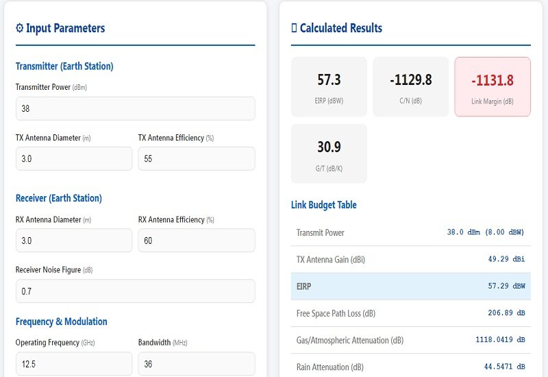
Enter parameters on the left panel and observe all derived outputs update automatically.
📖 Key ITU-R Formulas Used
⚙️ Input Parameters
Transmitter (Earth Station)
Receiver (Earth Station)
Frequency & Modulation
Path & Environment
Additional Losses
All outputs update automatically when you change any input parameter.
📊 Calculated Results
Link Budget Table
| Transmit Power | — |
| TX Antenna Gain (dBi) | — |
| EIRP | — |
| Free Space Path Loss (dB) | — |
| Gas/Atmospheric Attenuation (dB) | — |
| Rain Attenuation (dB) | — |
| Cable/Waveguide Loss (dB) | — |
| Miscellaneous Loss (dB) | — |
| Total Path Losses (dB) | — |
| Received Power (dBW) | — |
| Received Power (dBm) | — |
| RX Antenna Gain (dBi) | — |
| System Noise Temperature (K) | — |
| G/T Ratio (dB/K) | — |
| C/N₀ (dB-Hz) | — |
| C/N Required (dB) | — |
| Link Margin | — |
Link Budget Visualization
Status Assessment
📋 Modulation & Required C/N Reference
Required C/N ratios depend on modulation scheme, FEC rate, and desired BER (typically 10⁻⁶):
| Modulation | Required C/N (dB) | Typical C/N₀ (dB-Hz) |
|---|---|---|
| BPSK | ~1.0 | ~88 |
| QPSK | ~2.0 | ~93 |
| 8PSK 1/2 FEC | ~5.0 | ~105 |
| 8PSK 3/4 FEC | ~6.0 | ~110 |
| 16QAM | ~9.0 | ~125 |
| 32QAM | ~11.0 | ~138 |
| 64QAM | ~14.0 | ~155 |
Values are approximate. Actual requirements depend on implementation and channel coding.
📚 ITU-R Reference Standards Used
ITU-R P.618 — Propagation Data Relevant to Satellite Services
- Provides statistical rain attenuation data for Earth-to-space links
- Used to determine rain margin based on availability (e.g., 99.99% uptime)
- Defines precipitation figures for various locations worldwide
ITU-R P.676 — Attenuation by Atmospheric Gases
- Models gaseous attenuation from oxygen and water vapor absorption
- Frequency-dependent specific attenuation (peaks at 22 GHz and 60 GHz)
- Depends on pressure, temperature, and water vapor density
ITU-R P.837 — Rain Propagation Data
- Provides specific attenuation coefficients (a, b) for rain at various frequencies
- γr = a · Rb where R is rain rate in mm/hr
- Coefficients vary by frequency range and polarization
ITU-R P.2109 — Earth-Space Path Attenuation Due to Rain
- Defines slant path length through rain for given elevation angle
- Lrain = γr × Lslant
- Lslant ≈ hrain / sin(θel) for small angles